理解 MSBFIRST(最高有效位)和 LSBFIRST(最低有效位)
Understanding MSBFIRST (Most Significant Bit) and LSBFIRST (Least Significant Bit)
理解 MSBFIRST(最高有效位)和 LSBFIRST(最低有效位)
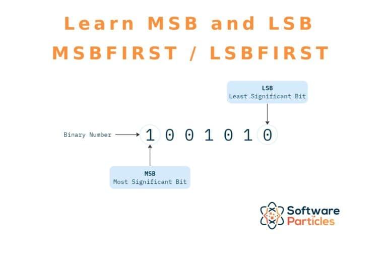
In this article, we explain the concepts of MSB (Most Significant Bit) and LSB (Least Significant Bit), along with MSBFIRST and LSBFIRST. Finally, we provide a demonstration of how the use of MSBFIRST and LSBFIRST affects the outputs of shift registers.
在本文中,我们解释了 MSB(最高有效位)和 LSB(最低有效位)的概念,以及 MSBFIRST 和 LSBFIRST。最后,我们展示了 MSBFIRST 和 LSBFIRST 的使用如何影响移位寄存器的输出。
MSB and LSB
最高有效位和最低有效位
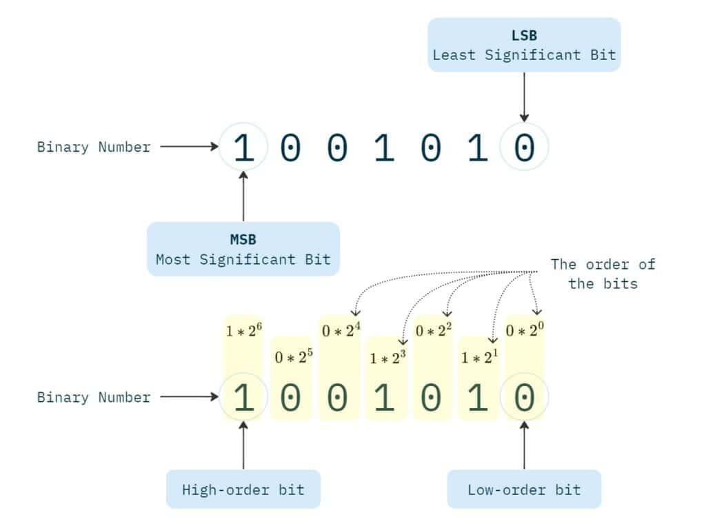
The MSB, or Most Significant Bit, refers to a specific bit in a binary number. The Most Significant Bit, holds the higher weight or value in the binary representation. It is also known as the left-most bit or higher-order bit. In contrast, the LSB, or Least Significant Bit, refers to the lowest value bit in a number, making it the right-most bit or the low-order bit.
最高有效位(MSB)是指二进制数中的一个特定位。最高有效位在二进制表示中具有更高的权重或值,也被称为最左边的位或高位。相反,最低有效位(LSB)是指一个数中值最低的位,因此它是最右边的位或低位。
MSBFIRST and LSBFIRST
In the serial transfer of data in electronics, when transmitting a binary number, we usually have to decide about whether to start the transfer from the leftmost or rightmost bit. This is referred to as MSBFIRST and LSBFIRST.
在电子学中,进行数据的串行传输时,当我们传输一个二进制数时,通常需要决定是从最左边的位还是最右边的位开始传输。这被称为 MSBFIRST 和 LSBFIRST。
For example, consider the shiftOut function in Arduino, which transfers a byte of data one bit at a time. The function includes a parameter (bitOrder) that allows us to specify whether the byte should be sent starting from its MSB or LSB.
例如,考虑 Arduino 中的 shiftOut 函数,它一次传输一个字节的数据,每次一位。该函数包含一个参数(bitOrder),允许我们指定是从字节的最高有效位还是最低有效位开始发送。
shiftOut(dataPin, clockPin, bitOrder, value)Configuring this parameter becomes more important when working with various digital components, such as shift registers. For instance, transferring a byte to a shift register starting from its Most Significant Bit will yield a different result compared to starting from its Least Significant Bit.
当使用各种数字元件(如移位寄存器)时,配置此参数变得更加重要。例如,从最高有效位开始将一个字节传输到移位寄存器,与从最低有效位开始传输,结果会有所不同。
74HC595 Shift Register with MSBFIRST and LSBFIRST
74HC595 移位寄存器与 MSBFIRST 和 LSBFIRST
In this section, we explore two distinct examples of utilizing the shiftOut function with MSBFIRST and LSBFIRST parameters to write a binary number to the 74HC595 shift register. The same principles apply across all other shift register models.
在本节中,我们探讨了两个使用 shiftOut 函数与 MSBFIRST 和 LSBFIRST 参数将二进制数写入 74HC595 移位寄存器的不同示例。这些原理适用于所有其他移位寄存器型号。
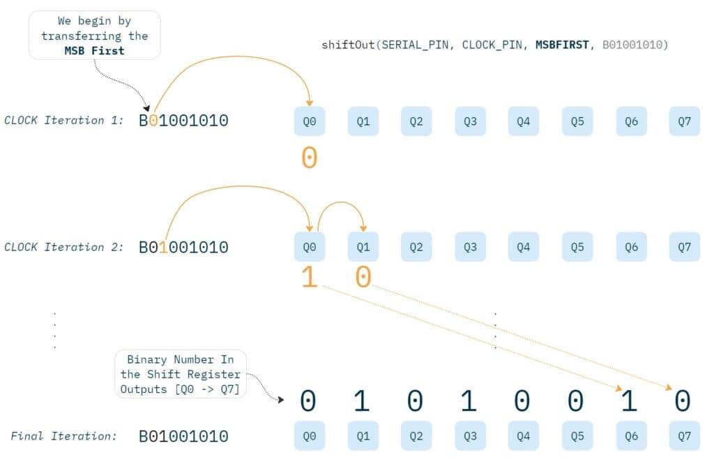
In the code below, we write the 8 - bit binary number ‘01001010’ to the shift register with MSBFIRST configuration:
在下面的代码中,我们将 8 位二进制数 ‘01001010’ 以 MSBFIRST 配置写入移位寄存器:
Shift Register - MSBFIRST Example#define SERIAL_PIN 4
#define LATCH 3
#define CLOCK_PIN 2

void setup() {
  pinMode(SERIAL_PIN, OUTPUT);
  pinMode(LATCH, OUTPUT);
  pinMode(CLOCK_PIN, OUTPUT);

  digitalWrite(LATCH, LOW);
  shiftOut(SERIAL_PIN, CLOCK_PIN, MSBFIRST, B01001010);
  digitalWrite(LATCH, HIGH);
}

void loop() { }
In this configuration, the shift register’s outputs will have the leftmost digit of the binary number ‘01001010’ in the Q7 output, with its rightmost digit at the Q0 output after the transfer.
在这种配置中,移位寄存器的输出将在 Q7 输出端有二进制数 ‘01001010’ 的最左边的数字,在传输后其最右边的数字将在 Q0 输出端。
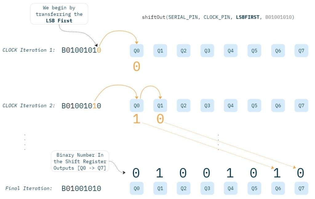
Similarly, the code snippet below, illustrates writing the binary number ‘01001010’ to the shift register, but this time with LSBFIRST configuration:
类似地,下面的代码片段展示了将二进制数 ‘01001010’ 写入移位寄存器,但这次使用 LSBFIRST 配置:
Shift Register - LSBFIRST Example#define SERIAL_PIN 4
#define LATCH 3
#define CLOCK_PIN 2

void setup() {
  pinMode(SERIAL_PIN, OUTPUT);
  pinMode(LATCH, OUTPUT);
  pinMode(CLOCK_PIN, OUTPUT);

  digitalWrite(LATCH, LOW);
  shiftOut(SERIAL_PIN, CLOCK_PIN, LSBFIRST, B01001010);
  digitalWrite(LATCH, HIGH);
}

void loop() { }
With LSBFIRST, we will have a different outcome, the shiftOut function will begin to transfer the number to the shift register by beginning from its rightmost digit. This way, the rightmost digit of the number ‘01001010’ will be located in the Q7 output, while its leftmost digit will appear at the Q0 output after the transfer.
使用 LSBFIRST 时,结果会有所不同,shiftOut 函数将从数字的最右边的数字开始,将数字传输到移位寄存器。这样,数字 ‘01001010’ 的最右边的数字将位于 Q7 输出端,而其最左边的数字将在传输后出现在 Q0 输出端。
涨知识

LTE Cat.1
Cat.1技术是LTE(Long-Term Evolution)技术的一种调制及编码技术,可以提供相对较高的数据传输速率,同时又具有低功耗、低成本的特点,可以为物联网设备的连接提供更好的解决方案。
评论:
Arduino-ESP32与ESP-IDF的版本对应表
Arduino-ESP32与ESP-IDF的版本对应表。
ESP32 + Arduino使用TFT_eSPI库
Arduino+ESP32上使用TFT_eSPI库快速点亮这个屏幕,驱动芯片ST7789
Arduino 数据结构: 队列Queue
Queue 库提供了一个通用的 C++ 动态队列实现,专为在 Arduino 项目中使用而定制。
小鹏浇花套件单机版程序V1.0.0
本程序是小鹏物联网智能浇花套件的单机版程序(不连接物联网),供同学们参考。

Arduino 数据结构: ArrayList
ArrayList 类是一个 C++ 模板类,它提供了 ArrayList 的实现,以便轻松存储任何指定类型的值。它允许使用索引进行高效存储和检索,支持排序操作。

ESP32 FreeRTOS 双核使用
ESP32系列(包括ESP32-S3)搭载Xtensa双核处理器,默认情况下Arduino框架仅使用单核运行用户代码,通过多核编程,可以充分利用硬件资源来提升系统响应和性能。
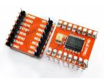
Arduino 和 TB6612FNG 驱动直流电机
TB6612是一款双路H桥型的直流电机驱动芯片,可以驱动两个直流电机并且控制其转速与方向,输入电压在3V~12V,因此在集成化、小型化的电机控制系统中,它可以作为理想的电机驱动器件。
Arduino-ESP32 Preferences库使用详解
Arduino-ESP32项目提供的Preferences库是一个专为ESP32设计的非易失性存储解决方案,它替代了传统的Arduino EEPROM库,提供了更强大、更可靠的数据存储功能。
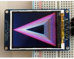
Adafruit GFX图形库的使用
用于Arduino的Adafruit_GFX库为我们所有的LCD和OLED显示器提供了通用语法和图形功能集。这使Arduino程序可以轻松地在显示类型之间进行调整,而不必花太多精力……
Arduino Serial 接收数字
在Arduino中,通过串行端口接收数字通常涉及使用Serial.read()、Serial.readString()、Serial.parseInt()等方法。
